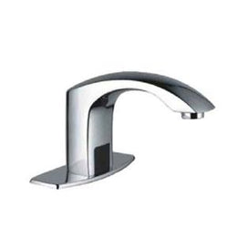
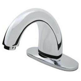
Capri Auto Faucet with Surround Sensor Technology
SKU: HDM-TC-AF-CAPRI-SSTMSRP: $507.00
Our Price: $390.00
The Capri AutoFaucet® conserves resources, reduces costs and promotes health and wellness. It is the best washroom faucet system you can buy. Equipped with our breakthrough Surround Sensor™ Technology, AutoFaucet delivers water only when needed, which results in water savings of up to 70 percent. The touch-free design creates a first-class patron experience while helping prevent the spread of germs. With industry-leading reliability, user-friendly performance, simple installation and cost effective operation, AutoFaucet is yet another innovative hygiene solution.
Warranty: Warranty: 3-Year warranty guaranteed against defects of parts and workmanship.Opperations: AUTO - enables automatic operation of valve. OPEN - maintains open valve position for sanitary flushing. To reactivate automatic operation, turn dial to auto position and then place hand under faucet and remove. Battery Power: 4D cell Alkaline (up to 3+ years life cycle) Mounting Hole: 7/8” to 11/8” Operating Water Pressure: 7-150 psi Operating Temperature: 35°F to 159°F (2°C to 70°C) Max Running Time: 15 Seconds Operations 1) “Surround Sensors” continuously scan the 3” detection zone around the spout. 2) When the user’s hands come into range of the sensor’s detection zone, the valve is activated. 3) After the user removes their hands, the valve closes. The circuit automatically resets for the next user. 4) Sensors will only detect animate objects.
Installation: IMPORTANT - DO NOT USE PIPE DOPE OR TEFLON TAPE FOR ANY FAUCET OR SUPPLY CONNECTIONS! Step 1 Attach both threaded studs (D) to the bottom of the semi-assembled cover plate. Step 2 Guide the semi-assembled faucet spout through the 3-hole 4” or 8” center set in counter or sink. Step 3 Finish securing the cover plate from underneath by placing the two metal washers (E) on to each of the threaded studs. Secure with hex nut (F) and hex nut (DD). Step 4 Secure the spout by using the following components in sequential order: a. Tab grounding spacer (G) (brass washer needs to be on top) b. Brass mounting nut (H) c. Sensor wire connection washer (I) [IMPORTANT: Make sure this washer’s tab is rotated 180° from the tab grounding spacer (G).] d. Brass mounting nut (H) Step 5 Connect the two 12” supply hoses (L) to the mixing valve (M). Place the rubber washer (R) into the mixing valve’s brass nut fitting (as shown) and then tighten to bottom of the valve control module (K). Step 6 Connect the earth ground wire (U) to one side of the U-tab. Then connect the yellow sleeved drain ground connector, located on the Grounding Isolation Wires (BB), to the other side of the brass U-tab. Step 7 Hand tighten the valve control module assembly to the faucet shank. NOTE: Make sure the black rubber washer is in the white plastic nut before connecting the valve control module to the faucet shank. Step 8 Mount the earth ground clamp to the cold water supply pipe. Step 9 Connect the longer green earth ground wire to the clamp tab. Step 10 Mount the drain ground clamp to the metal drain tail stock as close to the sink as possible. Step 11 Connect the brass plated end (black sleeved) of the green Grounding Isolation Wires (BB) to the drain ground clamp tab (V). Step 12 Connect the ring terminal on the green Grounding Isolation Wires (BB) to the stud with the hex nut (DD). Continue fastening with lock washer (CC) and hex nut (F). [NOTE: For single-hole mounted faucets remove the ring terminal wire with wire cutters.] Step 13 Connect the other end of the green Grounding Isolation Wires (BB) to the tab grounding spacer(G). Step 14 See battery compartment installation instructions below. Then connect the battery power connector wires together. Test the black sensor wire with your fingers. There will be a clicking sound coming from the valve control module indicating that the faucet is installed properly. Step 15 Connect the black sensor wire to the sensor washer (I). Step 16 Connect the water supply hoses (L) to the valve stops. Turn on the hot and cold water supply and test faucet. NOTE: · If the optional 6” extension hose (J) is used between the valve control module (K) and the faucet shank connection (to lower the unit down for accessibility), the rubber washer (R) is not required. · If this is an AC adapter installation, skip “Battery Compartment Installation” and use instructions supplied with the AC adapter. Battery Compartment Installation 1. Remove battery compartment cover by unscrewing the two Phillips screws. Inside the battery compartment (N) there are two large screws and anchors (O). Place the battery compartment (N) in a convenient location ensuring easy access. 2. Secure to wall using screws and anchors (O) or double-sided tape (P). 3. Install four (4) “D” cell alkaline batteries (Q). Replace cover on battery compartment. Connect battery box connector to valve power connector. Once power is established, you will hear a clicking sound when you place your hand under the faucet. 4. Turn water supply on. The water will automatically come on when you place your hand under the faucet. The water will stay on for a maximum of 15 seconds as long as your hands are under the faucet, and moving. The water will shut off after you remove your hands from the sensing zone or water stream. 5. Verify water supply connections are not leaking. Setting Water Temperature Mix 1. There is a temperature dial on the mixing valve (M). Use a screwdriver to loosen the screw on the dial. [To add hot water, turn the knob to the right or to the left to add cold water. ] 2. Once you have the desired water mix temperature, lock the control knob in place with a screwdriver. 3. There is a temperature adjustment on the optional thermostatic mixing valve (FF). Use an allen wrench to turn adjustment screw to add hot or cold water.
Automatic Faucet System • Delivering Cost-Effective Customer Delight... provides the user water ONLY when needed, resulting in reduced water usage up to 70% and associated costs — win-win solution. • World-Class Reliability... breakthrough “surround sensor” technology (no infrared) senses user from any angle, patented “dry” cam-gear technology controls water flow and eliminates sticking solenoid valves that cause dripping — trouble-free operation. • Ease of Installation... all mechanical and electrical components are contained in one covered housing for easy installation — customer convenience maximized. • Radius™ Touch-Free Technology... systems won’t corrode or fail because our proprietary “dry” cam-gear design keeps all electronics away from water flow. Technical Concepts’ exclusive technologies enable our systems to be the most accurate on the market delivering error-free, precise performance and are sophisticated enough to compensate for users and the environment.
Kit 2 Includes: Spout, valve control module and main supply hose (1/2” pipe x 3/8” comp. x 12” legnth) Kit 3 Includes: Spout, valve control module, mixing valve and hot cold supply hoses and main supply hose (3/8” comp x 3/8” comp. x 12” legnth) Kit 4 Includes: Spout, valve control module, thermostatic mixing valve and hot cold supply hoses and main supply hose (3/8” comp x 3/8” comp. x 12” legnth) Optional Accessories: 402188 Thermostatic Mixing Valve 490137 Extension hose for lowering Valve Control Module


